
AEROSPACE MANUFACTURING · TOOLING & SUSTAINMENT
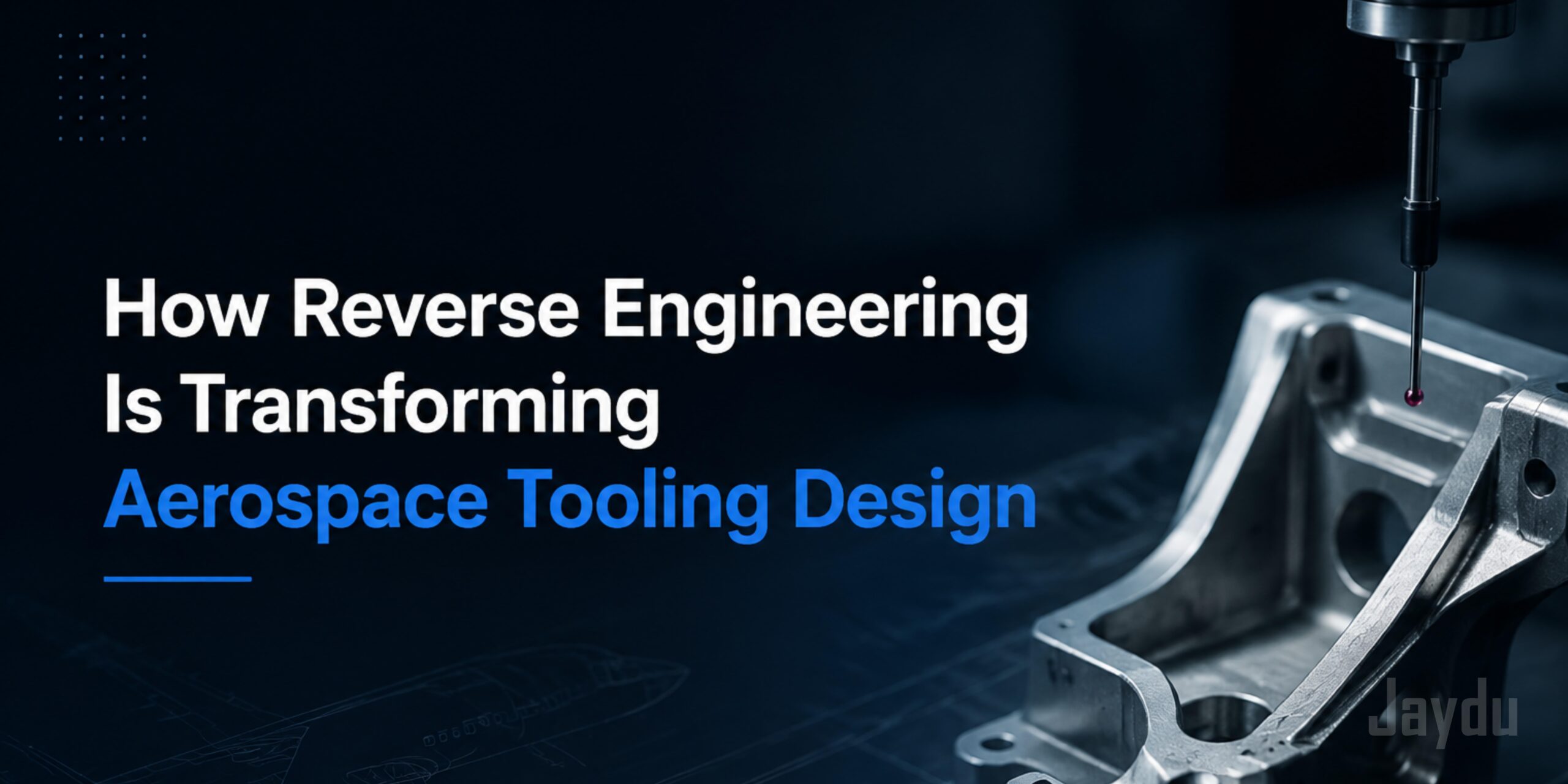
How Reverse Engineering Is Transforming Aerospace Tooling Design
From physical geometry to a reusable digital twin—reverse engineering is changing how aerospace fixtures, jigs, gauges, molds, and dies are designed.
THE SHIFT
Tooling design can now begin with reality—not assumptions.
Aerospace manufacturing runs on tooling — fixtures, jigs, gauges, molds, and dies that hold tolerances measured in thousandths of an inch across components that will spend decades in service. For just as long, designing that tooling meant starting from scratch: CAD models built from drawings, drawings built from specs, and specs that often no longer matched the part actually flying on the aircraft.
Reverse engineering is changing that order of operations. Instead of starting from paper, tooling teams are starting from the physical part itself — scanning it, modeling it, and working backward to a design that reflects reality rather than assumption. That shift is having an outsized impact on how fast, how accurately, and how cheaply aerospace tooling gets made.
LEGACY PROGRAM REALITY
The Problem Reverse Engineering Solves
Aerospace programs routinely outlive the documentation that describes them. A tooling engineer supporting a 30-year-old airframe might be working with:
Building new tooling from “official” specs can mean building tooling that doesn't actually fit the part.
Reverse engineering closes that gap by measuring the real, physical geometry and turning it into a usable digital model — effectively recreating the single source of truth that's gone missing.
THE REVERSE ENGINEERING WORKFLOW
From Physical Part to Digital Twin
The typical reverse engineering workflow for tooling design looks like this:
3D Scanning
Laser scanners, structured-light scanners, or CMMs capture the part's actual surface geometry as a dense point cloud, often accurate to a few microns.
Capture part geometryMesh and Surface Reconstruction
The point cloud is cleaned up and converted into a watertight mesh, then rebuilt into parametric CAD surfaces.
Build parametric CAD modelTolerance and GD&T Reconstruction
Engineers reapply geometric dimensioning and tolerancing based on function, not guesswork, since the scan alone won't tell you which surfaces are critical.
Reapply tolerances by functionTooling Design
Fixtures, drill jigs, and inspection gauges are designed directly against the as-built geometry, not an idealized one.
Build fixtures on real geometryThe result is a digital twin of the part that tooling can be designed around with confidence — and that twin becomes a reusable asset for the next repair, the next tooling iteration, or the next generation of the program.
WHY IT MATTERS
One accurate baseline. Three lasting advantages.
Sustainment
Saves old programs
Faster Iteration
Cuts lead time
Quality Control
Accurate baseline
AEROSPACE TOOLING SUPPORT